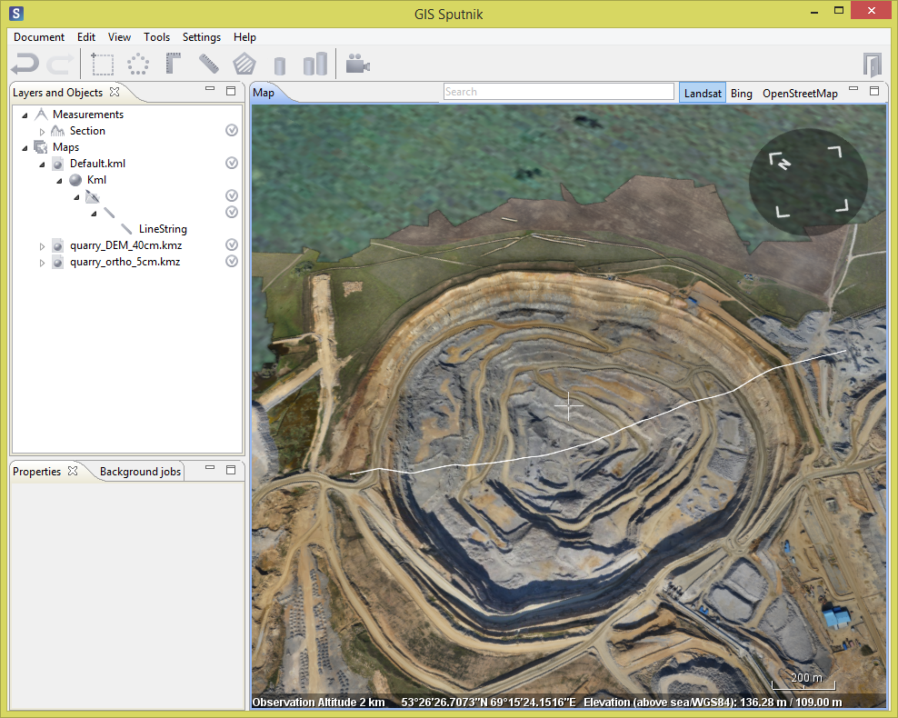
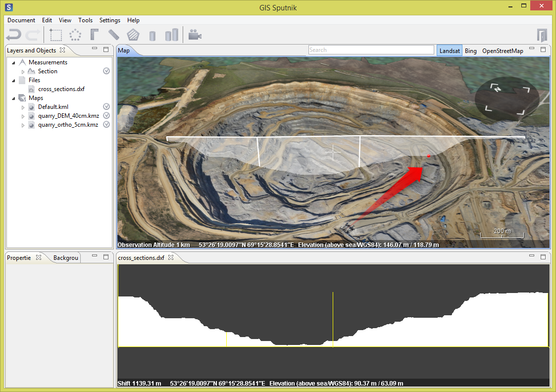
Cross section drawing generated in DXF format allows for cross profiles analysis. It can be used for road bends, quarry profiles reconstruction etc. DXF drawing can be afterwards imported to CAD software for the following measurements.
Sample datasets for this tutorial are available here.
To build the cross section follow the instructions:
- Run the Sputnik GIS and import elevation data in kmz or geotif format:
- Select the Cross Section tool (Tools > Cross section). Mouse cursor will turn to cross. Define the base line of cross section by clicking it on model:

- Select the appeared Section element in Layers and objects pane. Set the section precision in Properties pane.
- Press the Calculate button to start the Cross section reconstruction. Select the folder and filename in the appeared window.
DXF file will be opened automatically in the new window. Drag it to the most convenient place of the display to analyze the Map and Cross section windows simultaneously. The cursor movement over the cross section will be reflected with the red point movement along the 3d model:

Press and hold the left mouse button to move the drawing in DXF window, zoom the drawing in and out with mouse wheel to analyze the cross section metric data (height and length).
Corner ruler tool can be applied for dxf drawing. It will be simultaneously displayed on 3D model in Map window:

Cross sections tool
Cross sections tool allows for creating series of cross sections across a given line.
- Select the Cross sections tool (Tools > Cross sections).
- Define the base line. Cross sections will be generated perpendicular to it.
- Select the appeared Cross Sections element in Layers and Objects pane. Define following parameters in Properties pane:

- Section precision (m)
- Distance between the section (m): the step across the base line
- Section width (m) ? width of section
- Press the Calculate button to start the Cross sections reconstruction. Select the folder and filename in the appeared window.
Generated Cross sections will be saved automatically in the defined folder. Each Cross section will appear in Files folder (Layers and Objects pane). To view the DXF drawings double click any DXF element in Files folder.

In case you have any questions or suggestions please contact us: sputnik@geoscan.aero
