The drainage system is an engineering and technical structure intended for collecting and moving groundwaters in order to regulate the water balance of soils and create favorable conditions for the growth and development of plants. Deep drainage is a system of pipes (drains) laid beneath the ground. According to the Russian Federation Ministry of Agriculture data, in 2012 the total area of drained agricultural land was 4.8 mln ha, but a significant part of the reclaimed land is in unsatisfactory condition and needs reconstruction.
Geoscan specialists were assigned with a task of determining whether it is possible to recreate the plan of the underground drainage from the aerial photographs. In most of the agricultural lands, drainage systems were laid in the period from 1966 to 1991, after the adoption of the state program "On the broad development of land reclamation for obtaining high and stable harvests of cereals and other agricultural crops" in the USSR. Even if plans for the construction or reconstruction of a drainage network of the site are not lost, they, at least, require digitization and updating. In addition, since the service life of the network in most sites exceeds 30 or more years, it is very important to assess the status of individual network elements.
At first glance, mapping of underground drainage with the help of a drones looks like a futile venture. However, we suggest to study the process step by step and make sure that agricultural drones like Geoscan 201 Agro are fully suitable for reclamation tasks solving.
Since drains are laid at a depth of 0.8-1.2 m, their location can be remotely determined only indirectly - by the state of the vegetation. Sites of soil located directly above the drains, differ from more remote sites in terms of the conditions for plant growth, and primarily in terms of moisture supply. Fig. 1 shows a fragment of an orthophoto in false colors. Vegetation corresponds to pink shades, a higher density of vegetation corresponds to brighter shades.
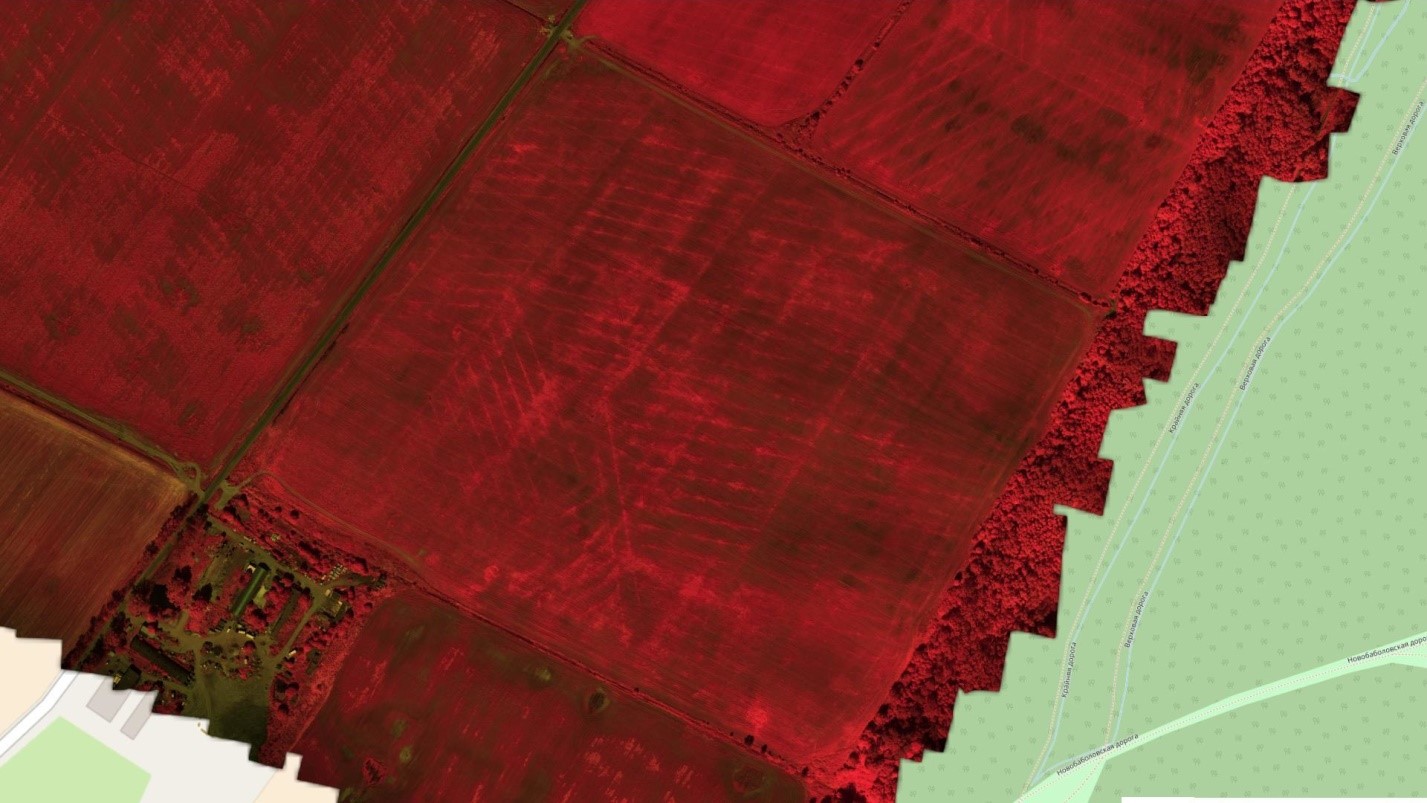 Fig. 1. Fragment of an orthophoto of the surveyed site in false colors.
There are noticeable brighter, even lines, located "herringbone" on the orthophoto characterizing underground drainage elements. Data is obtained with the use of Geoscan UAV equipped with a multispectral camera. The processing of the orthophoto is performed with Agisoft Photoscan. After loading of the obtained cartographic materials into the geoinformation system, the vectorization of the drains is carried out. For the convenience of the images interpretation, instead of composite images, vegetative index maps synthesized on their basis can be used. An example of the vegetation index map for the surveyed area is shown in Fig. 2. Indices that can be used for this task: NDVI, SR (Simple Ratio) NIR / RED, RED / NIR. All of them can be calculated with the help of the Photoscan raster calculator based on the survey data from the Geoscan UAV.
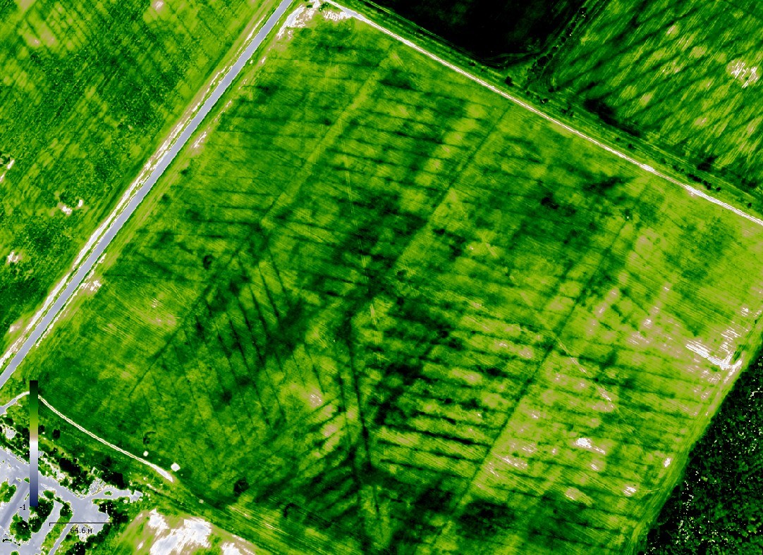 Fig. 2. Map of vegetation indices of the surveyed site.
As it is shown in Fig. 2, indices maps, in contrast to composite images, have a greater contrast and allow more precise marking of the drainage pipes location. The operator creates a vector layer and marks drains and collectors (see Figure 3). Open channels and drainage wells are interpreted visually (see Figure 4).
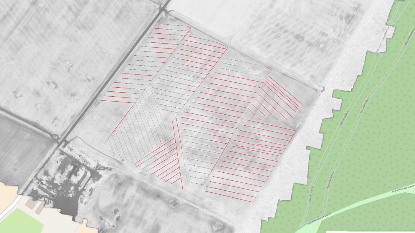 Fig. 3. A result of the interpretation - recreated plan of the drainage network
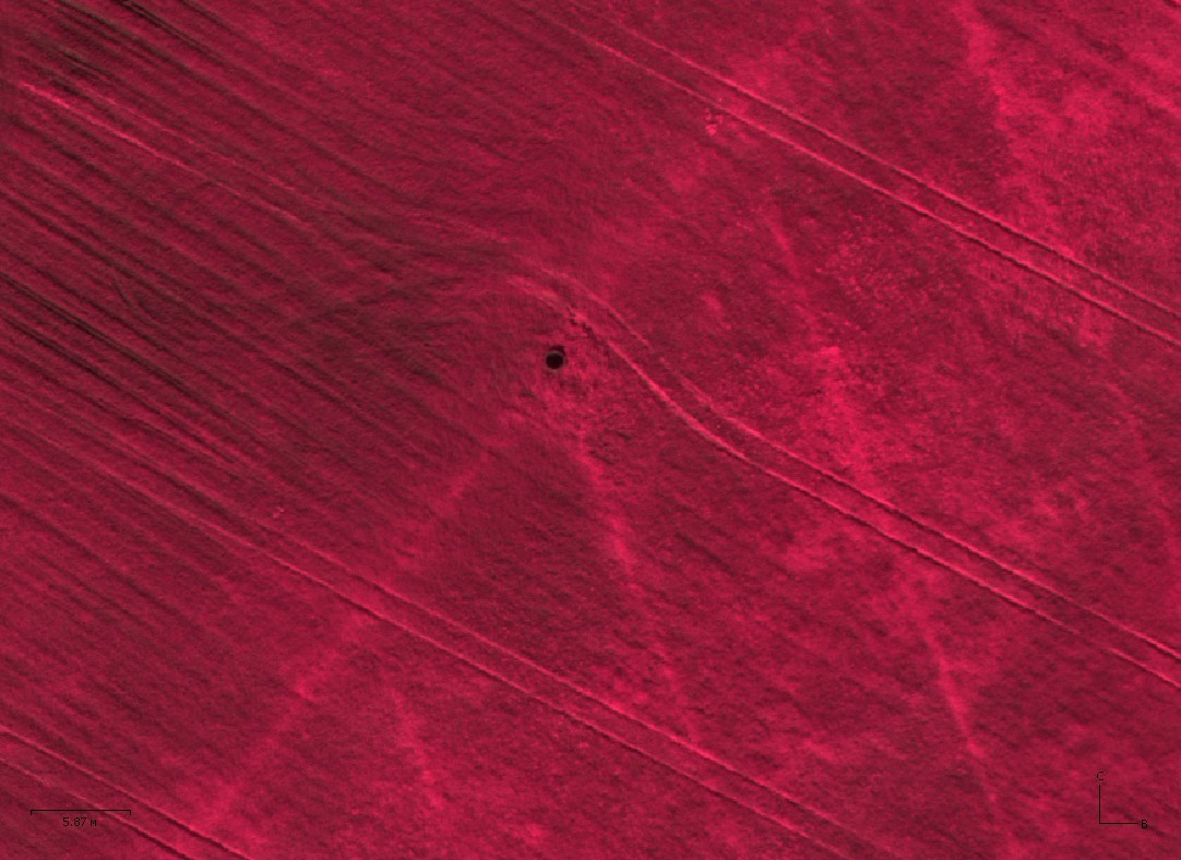 Fig. 4. Drainage well
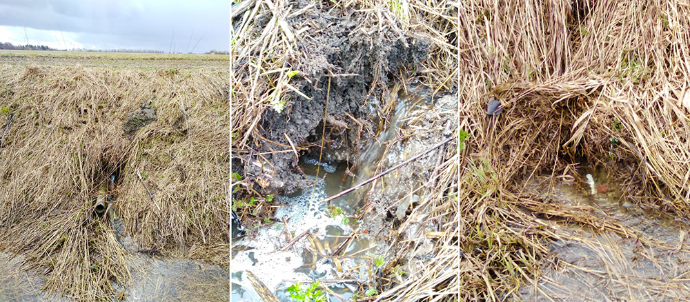
For the verification, two methods were used. The first method consists of the following: by the location of the collectors and open channels the coordinates of the points where the mouths of the collectors are presumably located are determined. Further, a bypass is made to confirm that there is actually a mouth in the specified location. During the bypass, photos were taken using a smartphone equipped with GPS. Fig. 5 shows the location of the places in which the mouth was found. The coordinates recorded by the smartphone at the time of the survey are used. The possibility of predicting the location of the mouths is an important result of the aerial photography. Look at the photo of the mouths - only one of the three clearly shows the pipe, and in the other two cases, the mouths are hidden by the grass cover, so without prior information about the location, the probability of their detection during the ground survey is very small.
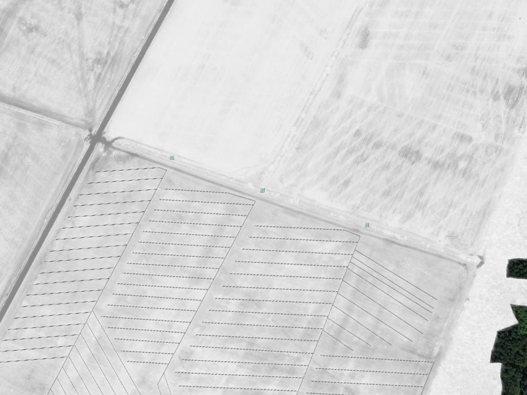
Fig. 5. Recreated plan of the drainage network and the locations of the mouths, detected during the ground survey.
The second way to test the method is to compare it with existing plans. A copy of the paper plan for the reconstruction of the drainage network of the surveyed site was georeferenced and transferred to WGS 84 for the loading as a separate layer (see Figure 6). As can be seen from the comparison of the data, the existing configuration of the drainage network does not coincide with the reconstruction plan: the topology of the network differs, the location of the wells does not coincide, part of the existing network is not indicated on the plan. Nevertheless, a number of facts confirm the validity of the applied method: the location of the majority of drains and collectors coincides, as well as the step of drains.

Fig. 6. Fragment of the digitized paper plan of the drainage network and a plan recreated based on the aerial survey data.
The obtained results show that materials obtained with unmanned aerial vehicles can be used to create plans for the determination of the actual location of the drainage network, including underground drainage systems. The obtained information can be useful not only if the reconstruction of the reclamation network is planned. The configuration of the drainage must also be taken into account at changing the configuration of the agricultural lands, as well as during the carrying out any activities that imply the transfer of soil. UAV data is also used for:
- detection of blockages on canals, beaver dams;
- determination of the places of forestry and shrubbery vegetation overgrowth;
- the search of the waterlogged sites;
- creation of the height maps, slopes maps, relief profiles
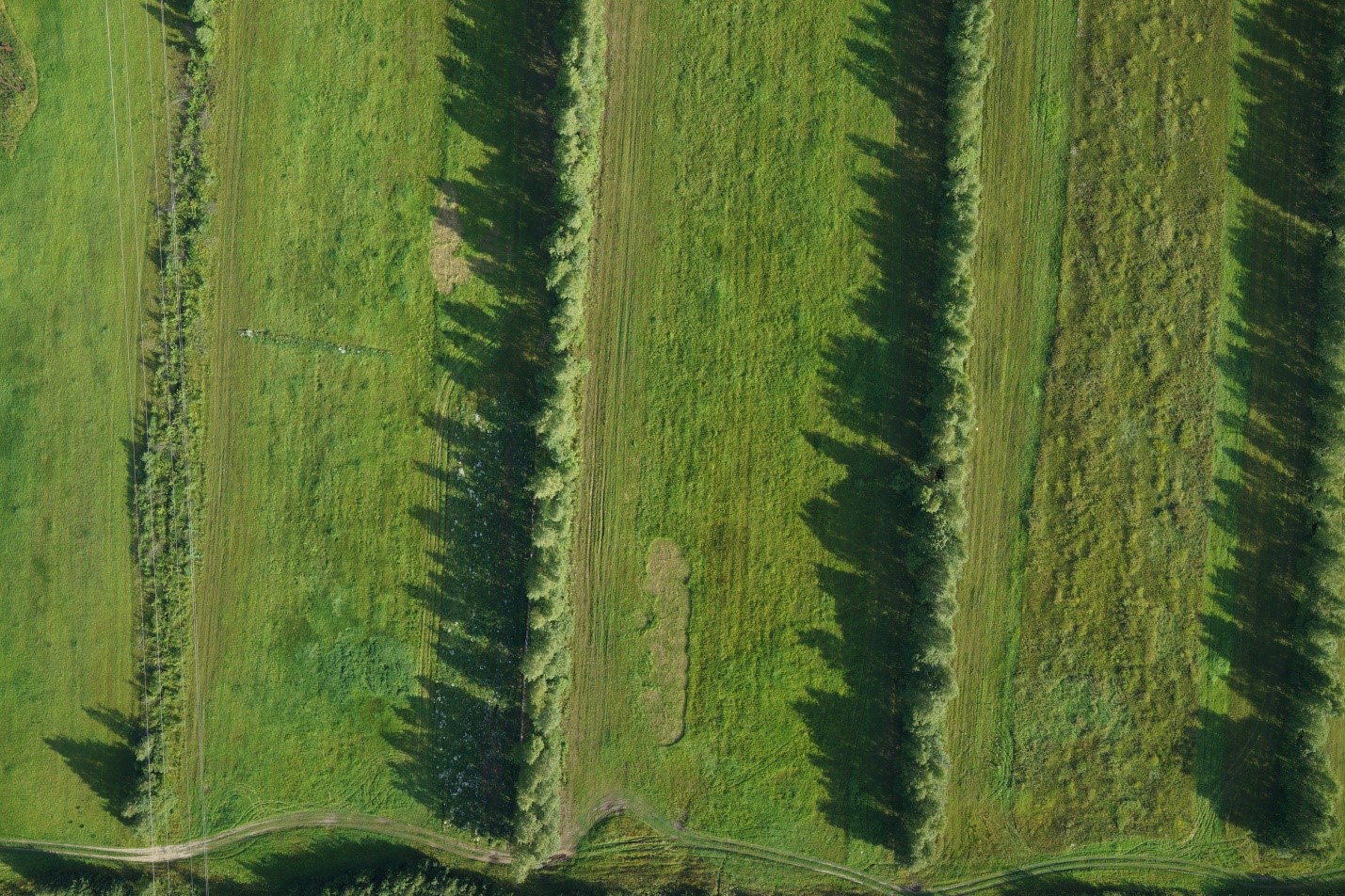 Fig. 7. Overgrowth of the drainage channels by the forestry and shrubbery vegetation.
Geoscan company expresses its gratitude to "Melioratsiya" LLC and its CEO, Tatyana Alexandrovna Cherdakova, for her help during the data preparation for the article.
